alright, i think im ok with how the films are turning out.
Im dropping to use 3 exposures, with +/-2 stops. ive tested the same frame using the same outputs on multiple different reels and with different scenes, and i couldn't see enough of a difference between 3 and 5 exposures to justify the extra time and space thats needed.
For a 50ft reel its taking up about 360gb for the raw photos when using 5 exposures, and only 180gb when using 3, and that increases 3x after converting to tiff.
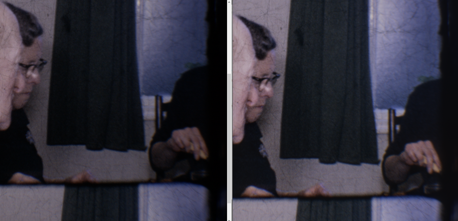
The image on the left is the single exposure capture at 0EV.
The image on the right is the 3 bracket "hdr" exposure, +/-2EV.
None of the images have had post processing, the left is the tiff output from raw, and the right is created using exposure fusion using enfuse.
There isn't a massive difference, i was expecting more to be honest. But you can still see some improvements, the 3 exposure version has more detail in the curtains, and the person on the right of the image wearing the black shirt, on the left image its pure black, but on the right, i can kinda make out a fold in the shirt. Maybe im just imagining things🤷♂️
Anyway, im gonna start the rest of the process after converting all these files.