
Sad News Alert
Moira Rose is DEAD!
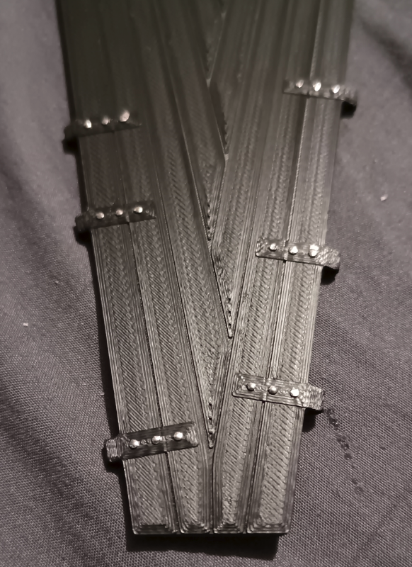
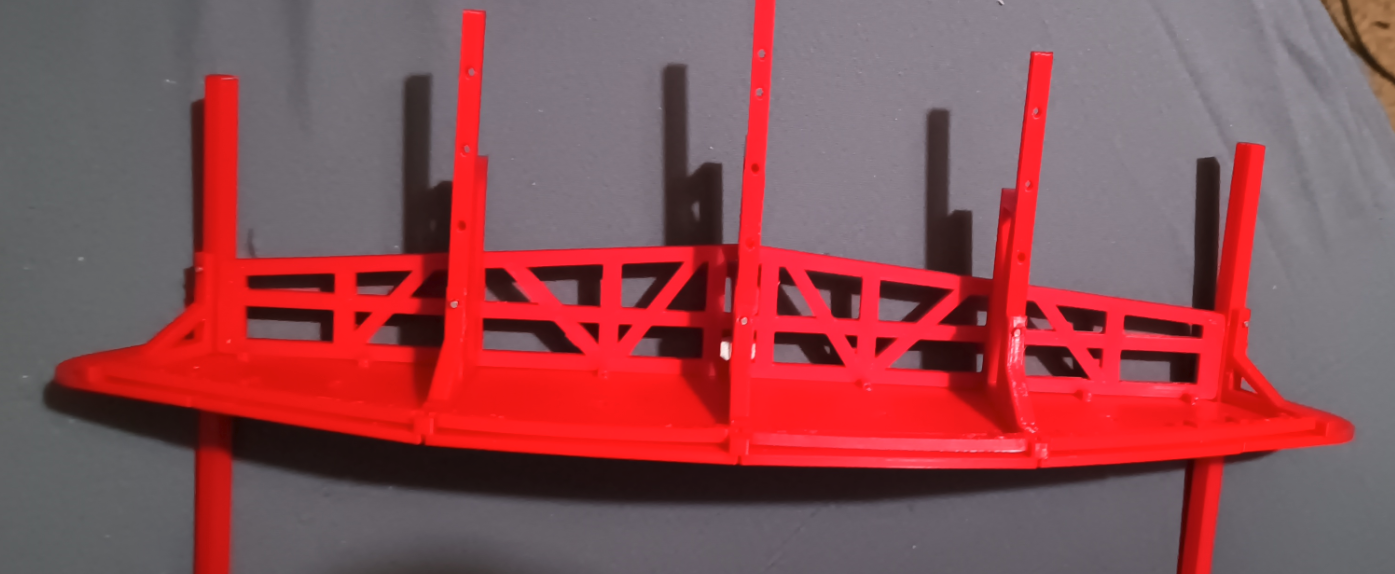
The test walkway is finished, and it fits... REALLY well. Like, it dont wobble a single millimeter.
I was thinking about putting a little more a gap between the slats, but i think its ok as it is.
The only problem with the new walkway is that i have to reprint the shutters, the walkways are slightly taller, so i have to adjust the shutter heights.
Im printing a couple of walkways to see if they fit as good as i hope they do, but im wondering if maybe i should use the textured print bed in the future, i have a feeling the smooth bed is gonna made the "wood" / surface a little too perfect..
I REALLY disliked the old walkways i designed, They was unstable and non planar, which made them a complete bitch to print. So ive spent WAY to much time redesigning them. They actually look somewhat like the real thing now 😂
Riddle me this.
Print WITH a raft, takes 59 minutes, without a raft... 1hr 22min... wtf is that about?
I was looking at the old tyres and decided i didn't like that it had no rim, so i added a one.
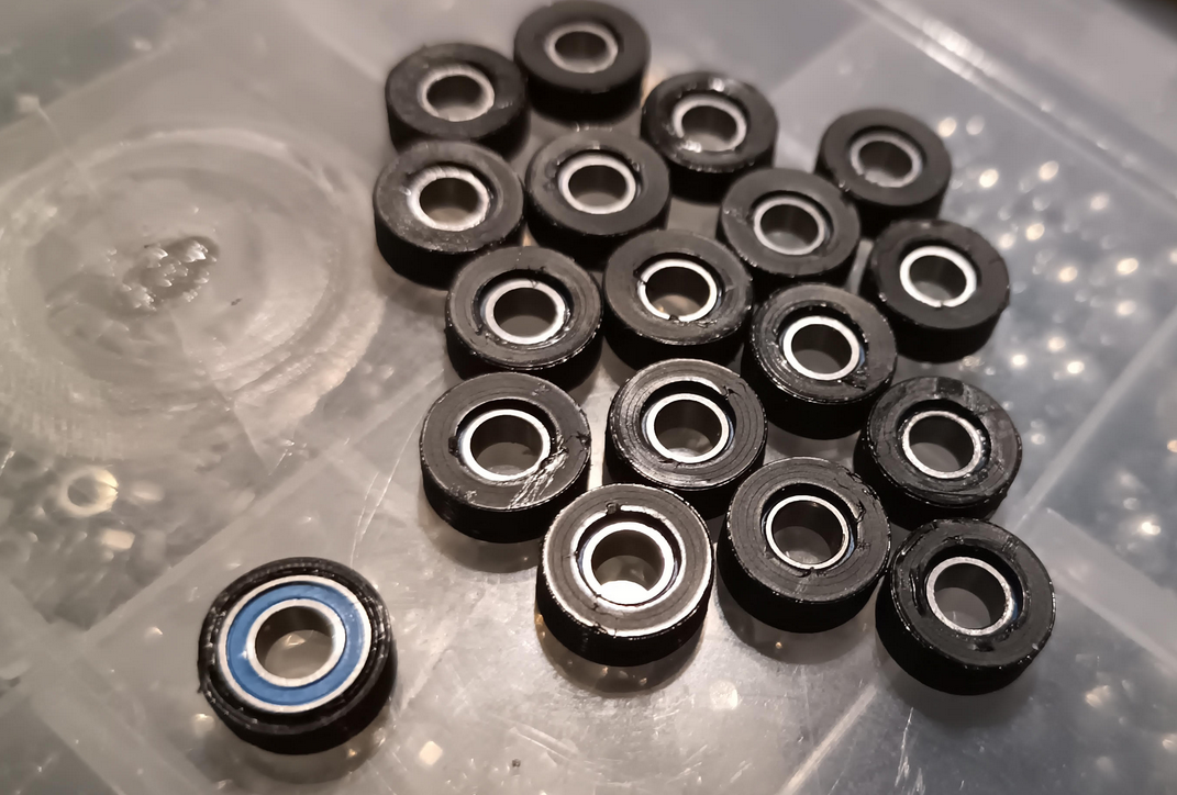
They kinda look like shit, but im ok with that, they look nice and used, kinda 😂
The weird shininess on the rim is from Super glue, Looking at it now, i realize i could have just made the inner diameter smaller and they would have probably stayed put without clue, to late now lol
I didn't give the tyre a rim on both sides because it would have needed supports, and im not sure im ready to tackle supports on TPU 😭
Gluing the rims is a very quick way to have all of your fingers covered in superglue😭
Last night i spent WAY to long fucking about with my printer trying to get the zoffset working correctly, no matter what i tried i could not get the printer to save the z offset and load it, eventually i gave up and just set the z offset in the start gcode for the printer. I have no idea why, but despite the config looking correct, and saving correct, it would revert back to the old z offset, its like it was just ignoring what was in the config. I even reverted back to an old config from july, and it still used the wrong offset 😭
ANYWAY, Im printing new platforms, and because ive never tried the ironing feature in orcaslicer, i figured i would give it a go, and i like it, alot. It adds like an hour to the print time for 3 platforms, but i think they look better.
Here is without ironing
This is with ironing
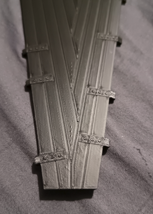
I think it looks way better personally. Yeah, its not perfect, but nor are the real platforms. I used that chrome pen i got on the little bolt head things, im kinda liking them. I will probably put them on all platforms, but im undecided if i want to do it with the ring on the car platforms.
Talking of platforms, im really not sure what colors to use, i am basically set on black at the moment, but im thinking of using a different color for the car platforms. Im currently using blue and yellow, but im not really a fan, i did look around and most waltzers use black, probably cause of dirt / grease and what not.
I did order "Royal Gold" filament, which looks really nice, but im not really sure i want entire platforms in that color... 🤷♂️
ok, Im going to do a 3 pronged attack, ive moved the hinge bar holes and the surrounding material 0.1mm outwards, which will give me a tiny little bit more material, and ive increased the size of the pin holes to 1.8mm, If neither of those solve the problem, ive ordered a long ass drill bit from amazon, so i can drill the holes to 2mm, which should give way more space than needed... unless im completly wrong and this is a waste of time and money 😭
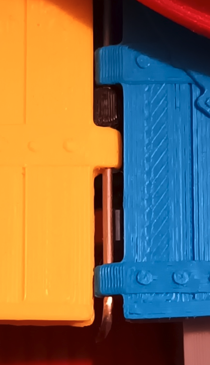
Oh and incase your wondering, this is how much material i have to work with...
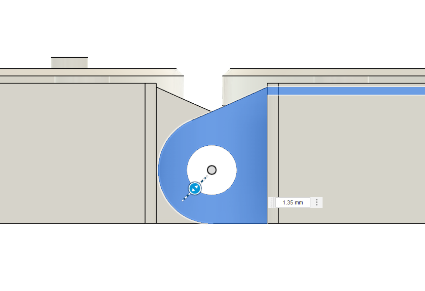
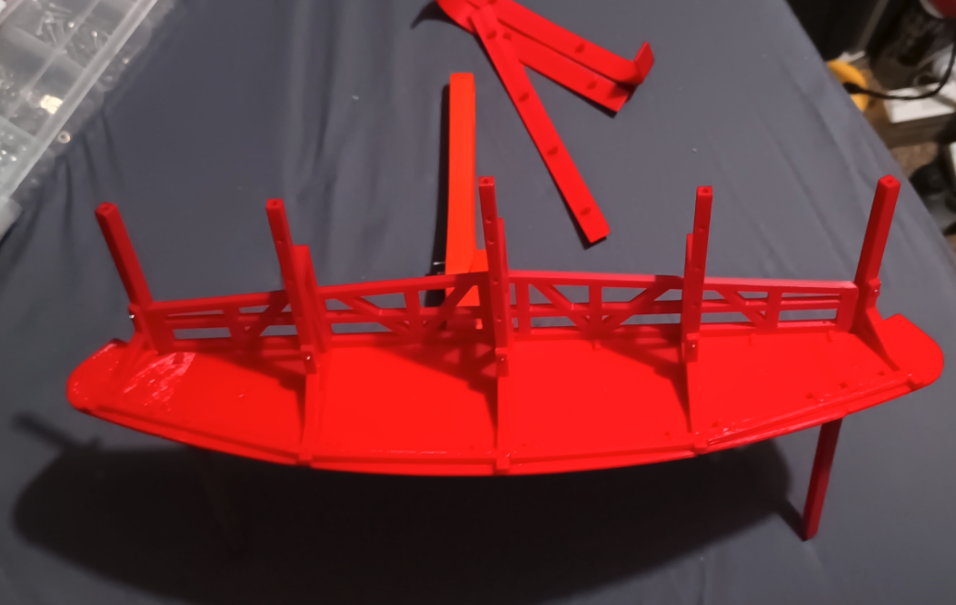
heres the thing, im not very good at math. But i had a feeling that i was on the wrong track when i was trying to find out why the wheels didn't meet the track in all three valleys of the waltzer.
Last night, like a dumbass i spent way to long aligning the platforms in cad, adjusting them to be in there resting position ect ect, but then i realized, i didn't actually need to do that.. i have the fucking model in front of me. So i pulled one of the hinge pins on the model to see how much of a gap would be left when all the wheels are touching the track...
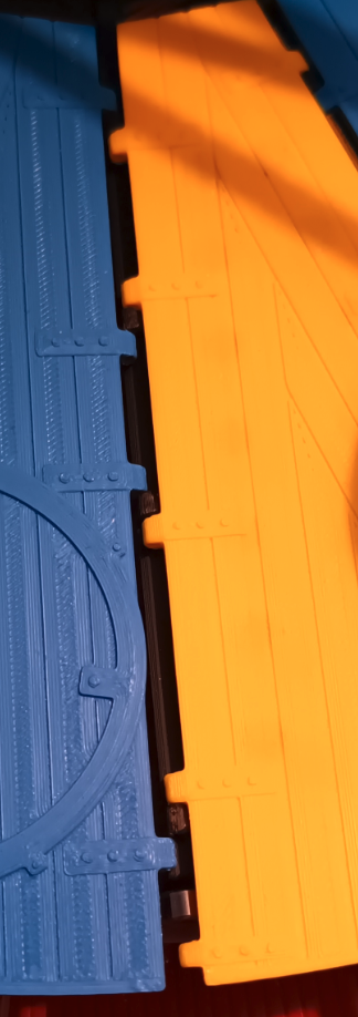
And now i can see why they wasnt bottoming out, without the hinge pin, there is a gap in the platforms.
This is what it looks like when connected to another platform
I think i have two options, option one is to increase the size of the platforms just enough to cover the gap, or option two is to increase the hinge bar hole tolerance on each platform and hope that it it loose enough to fill the gap.
Im really not sure which would be best. Looking at the photos, it seems the gap gets narrower as it goes towards the middle of the machine, So im not sure if increasing the platform size would work as i hope, if i increase the platform size, wouldnt the part closest to the middle be to close to each other?
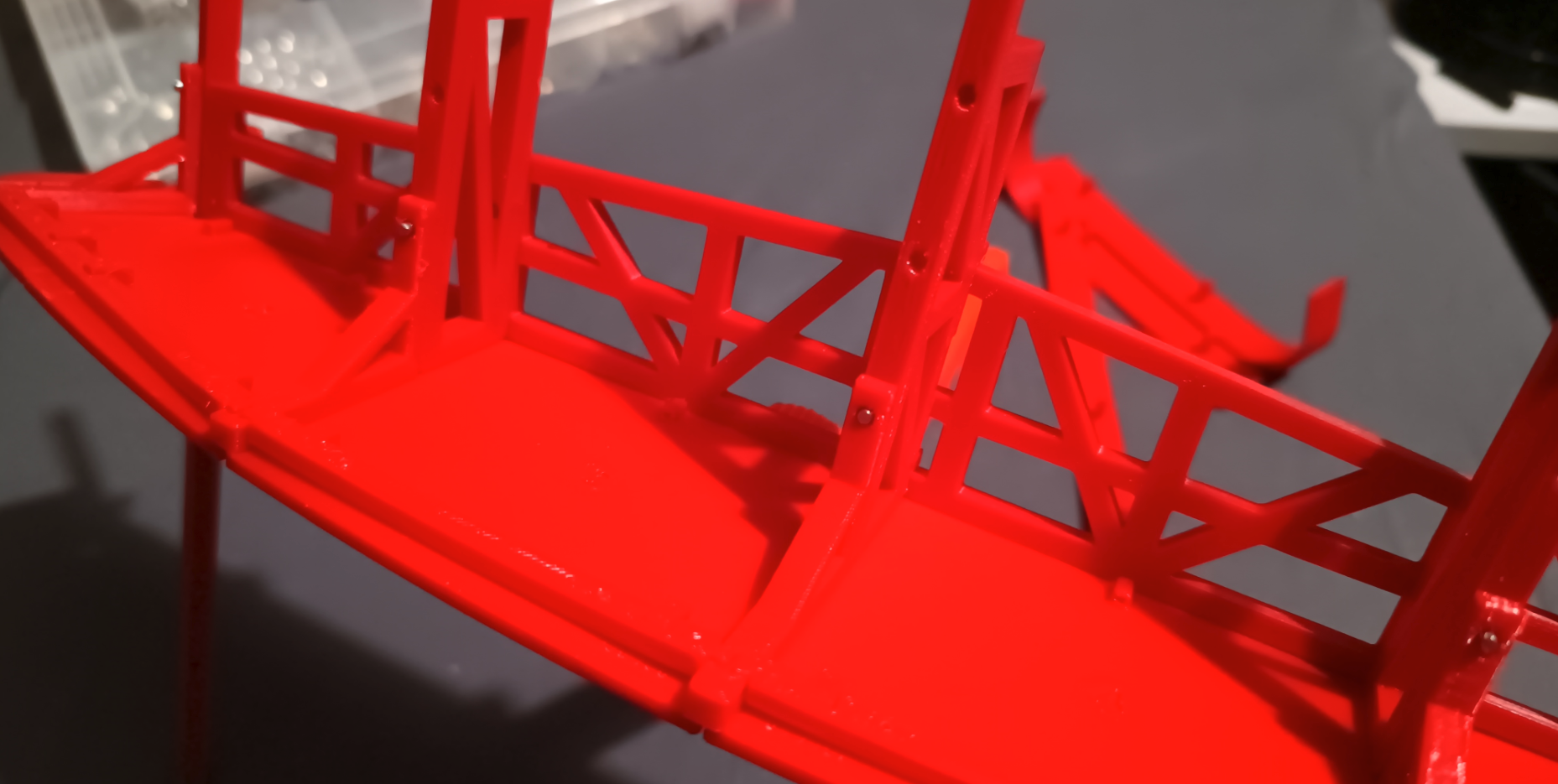
On the other hand, if i increase the hole size for each platform, it might not be enough in total to fill the gap, and i dont have much material to work with, even if i redesigned the platform hinge holes... hmmm...
I think im going to try option 2, increase the hinge pin hole sizes, but im going to do it with 3 platforms, and keep the rest of the original platforms, that way i can test to see if it actually works, if it does, then i can reprint all the platforms. It will take a long ass time, but ive been pretty lucky with the platform prints, ive only had 2 revisions of them, so this will be the third lol
At the widest point in the gap, its 5.13mm without the pin, and 2.94mm with the pin engaged. So 2.19mm difference, so i need to make up that 2.19mm distance by increasing the tolerance on the platform hinge holes enough to fill that 2.19mm gap, so each platform hinge holes should be increased by 0.122mm? right? hmm...
This post probably makes little sense. so im going to end it here lol
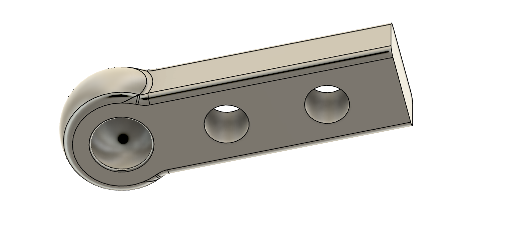
Im printing new hinge bars for the tow latch thing. I increased the inner ball to 4.5mm, as it was a little tight. Something else i tested, was printing the tow thing with pla, and after running a deburring tool around the hole for the pinhead, it popped right in, so its completely possible to use pla instead of tpu.
Im going to try the TPU ones and see how they hold up, if i need to, i can always switch to PLA.
I printed a new pin wheel as the current one has bigger holes than the new pins need. The holes in the new one were basically non existent. I made the 0.8mm diameter as the pins are 0.6mm, but they were filled solid. I managed to drill 3 of the holes out using a 0.75mm drill bit, but my hands were cramping up. So im gonna print a new one, this will have 1mm holes, which will hopefully actually be holes when printed.
I have no evidence of this, but im pretty sure the way i am connecting the platform hinges to the main pin wheel is causing me issues with the platform wheels not making full contact with the tracks in the valleys.
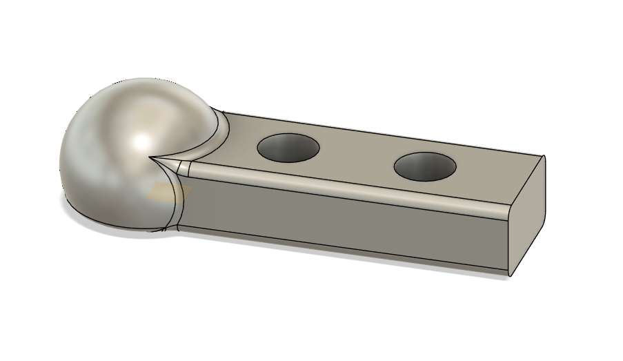
On the real ride, they use a tow bar connector (not sure of its actual name), the kinda you connect a trailer to your car with. It allows the hinge bars to move in all directions, where as my connections only allow movement in 2 directions, up and a little bit down, as well as left and right. The "little bit down" is that part that i think is cause my issue. I think the bar is hitting the side of the pin wheel and as a result, the hinge bars done angle low enough for the wheels to hit the track.
Originally, i thought it wouldn't be possible to replicate the joint at such a small scale, and if i could, i couldn't see a way i would be able to lock the ball and socket into place. Except, now, i have TPU😈
I just designed a test piece to see if its even possible, and it worked incredibly well. A few adjustments and i think it will be pretty damn good.
I tested it on a pin with a 4mm bead head, like this.
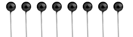
Except my pin head was all rough and out of shape, like me. Anyway, ive ordered some of these pins on amazon and ill see how they work out, assuming they are as smooth as in the image, it should be fairly well. If not, ive ordered some steel ball headed pins, the only problem is, i cant find with a ball that is larger than 2mm diameter, So ive got the 2mm diameter ones, I have my doubts about these working, but if they do, they should be much better than the plastic ones.
I have no idea if that made any sense, but it does to me, so 🤷♂️
Just printed a few tyres to test the tpu... I completly forgot about the whole "Z Seam" thing... So the tyres have a lump on them. Im gonna try scarf joints and see how that goes
Today i learned that TPU sticks EXTREMELY well to PEI Build plates 😭
Ive been looking around at the best way to sound dampen the wheels on the ride. Obviously, on the real ride they use rubber wheels, but on my model, its just bearings, so metal on plastic, which when you have 50 odd wheels gets kinda loud. I have seen some other waltzer models and they seem to use lego wheels, but based on my measurements, they are a little to big. So i think im gonna pull the trigger on a filament dryer and some TPU and see how that goes. From some searching, tpu seems to be a good sound damper, so... might as well give it a try🤷♂️
Ive redesigned the canopy panels, and made some more adjustments.
I increased the size of the canopy overhang a few mm.
The panels are now in 2 pieces, this enables the pcb to be included for the lights.
Moved the number around to hide them a little better.
Added a hole in the top of the panels for wiring to the pcb.
Oh, i was looking at some pictures and i wasn't happy with the height of the canopy bezel, So i have increased that 4mm.
I added a bit of a tolerance gap for the crossbeam dovetail slots. If the crossbeam was raised a little to much, it would start to bend. It only happened because i was printing with supports for that part, and the support scaring added thickness where there should have been any.
I think im actually done with the canopy now (apart from the pcbs), for a while anyway.
Im mentally planning the pcbs for the front canopy.
Im not sure if i want to have 6 2 layer pcbs or 3 4 layer pcbs.
The panels on the canopy are mirrored, so it should possible to just put the led layout on both sides, that way 3 pcbs will work with the 6 panels, But its been a while since i ordered 4 layer pcbs, i cant remember if they was considerably more expensive than 2 layer.
I'm thinking about starting to layout the pcbs for the front ceiling panels. The pcb layout would dictate the canopy led layout, so im not putting the cart before the horse, and it would give be a break from modelling for a few days.
Front canopy has been printed. Sorry for the shit photos.
I will show a (hopefully) better picture tomorrow. I cant attach the canopy bezel until the 1mm rods show up.
I dont think im prepared to tackle the front signage yet, I'll probably think of something else to work on 😂
I had a load of spare 1mm rod and id be buggered if i can find them😭
Thankfully they are fairly cheap
Showing posts 41-60 of 333