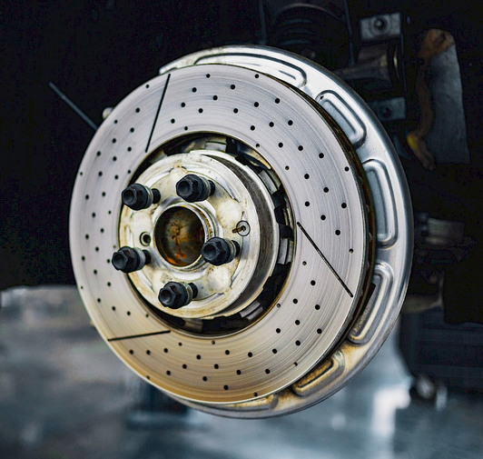
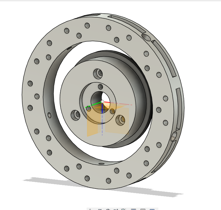
Im designing something in fusion, its a spin the wheel thing... and i realise, it just looks like a cars breaks or whatever... I think i re-invented the wheel 😭
Moira Rose is DEAD!
Im designing something in fusion, its a spin the wheel thing... and i realise, it just looks like a cars breaks or whatever... I think i re-invented the wheel 😭
I tried the waltzer the other day, for some reason, even tho i havent changed the size of the platforms, for some reason, they are too big? The yellow and blue platforms where a little too small, and now, those same platforms reprinted, are too big... It makes no sense.
Anyway, i felt deflated after that, so its on the shelf again for an unknown length of time. I was doing quite well on it too, i had the canopy done, the walkways, and the paybox / motor connection, which i dont think i posted on here tbh. 😭
Someone should make a mod for filament dryers that is an "MMS", Manual Material Selector.
It should be a switch you flip on the filament dryer, when flipped, it cuts the current filament and starts feeding the new filament, no purging, no layer changes or what not, infact, the printer doesn't even need to know this modification exists.
Is it any use? Nope, but its pretty cool.🤷♂️
Im still awake. I just poked the walkway to see if the pva has completly disolved yet, which it hasnt, but its infintly better than a few hours ago.
I wonder if warm water would do it faster...
I wonder if PLA can go in the dishwasher without warping 😂
On the walkways, there is a line, usually yellow, used as a "hey dont cross this when the ride is moving" line. I dont trust myself to paint a straight line, so im doing an experiment.
I tried to use masking tape to mask off an area and paint it, which worked, but the paint seeped up lines left on the 3d print.
So im trying this other way i just concocted in my head.
Ive placed some tape where i want the line to be, painted over the tape and the surrounding area with PVA glue, then i removed the tape, leaving the area i want painted, exposed. I then painted that area and left it to dry for a few hours.
The good thing about PVA glue is, its water soluble, which means, if my theory is correct, i can wash the glue off, and leave just the line of paint.
I just put it in a bowl of water, and the pva is dissolving.
I gave it a bit of a helping hand with a brush, but i was a little too aggressive and some of the paint came off. The fact the paint only dried for a few hours probably didnt help😂 im pretty sure it says on the bottle it can take 24 hours to fully dry😭
Im gonna leave it in the bowl overnight and see how it is tomorrow. I noticed earlier that the glue in the gaps of the print wasnt dissolving, so if its gone by the time i wake up, ill give the whole experiment another shot, but actually let the paint fully dry for a day this time.
Im REALLY tempted to get an ultrasonic cleaner, not just for the glue, but for cleaning PCBs and what not too...
I dunno wtf is going on. I reprinted the platforms, reverting back to the original design, except enlarging the hole, and i put them all in place and they are too big... which makes no sense, ive measured the old and the new and they are identical except the hole size, so how are they taking more room... 😭
Im kinda starting to like the black and yellow look i currently have setup. Maybe i will try that royal gold filament i have.
I brought some nice brass 1mm rods for the hinges on the waltzer, but they bend really easy and have very little spring. Im not sure how they will hold up tbh
I got an anti vibration mat for my 3d printer.
I got it to see if it would let me push my speeds a bit more, but it helps with sound too lol
im so fucking confused. I just connected all the old smaller yellow platforms, with the new bigger than expected platforms and they still overlap.
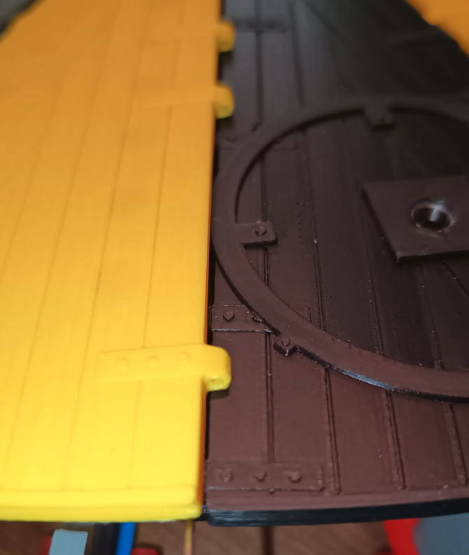
Its overlapping by 3mm now, but i dont understand how. Maybe i just need to use bigger holes? Maybe the extra 0.16mm on each side isnt needed at all, and it just needs more wiggle room....
I just realised, i can use the original yellow platforms to see if everything lines up correctly, because the old platforms have no adjustments, and the new ones have double what it should be, it should semi cancel each other out and leave me with the desired extra width😈
It seems i have made a mistake...💀
When i connected all the platforms, they overlapped by about 3mm 😭
So im going to have to reprint the platforms again, which sucks ass, cause they take SO FUCKING LONG.
I just looked some photos i took of the original blue and yellow platforms, and they wernt wide enough, which is why i reprinted them wider, but looking at the picture, i only needed to make up about 3mm in total, where as the new platforms are juast over 5mm wider, so double the needed size.
I think what happened was, i adjusted the hinges on both sides of the platform, with the total value for the size of the platforms instead of half the value.
So in theory... if i only increase it by 0.8mm on each side, it should give me the right size in total.
This probably makes little sense to anyone else, but i know what i mean 😭
I swear im my own worst enemy.
Im building the waltzer up finally, and im realizing how much i dislike the lower crossbeams. They dont really stay where i put them, and since i redesigned the upper crossbeams, the lower ones now feel even crappier. hmmmm
What if, when you die, your forever stuck in that second you died. So if you die in your sleep, you will be stuck in a constant sleep💀
Ive modified the rafters to have the bulbs print directly on the rafter. The old rafters had the rafter and the bulbs printed separately, then superglued in place.
The reason i changed the rafters is because I decided i didn't like the grey rafters ( and im trying to avoid building the waltzer through fear of something being wrong or it being right and me being closer to finishing it, which will then leave me with nothing else to do😂), i would have liked a more charcoal like color, and ive decided on the colour scheme for the ride, so i figured black would be the best choice.
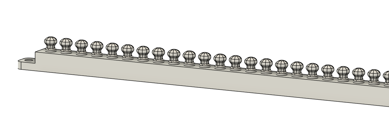
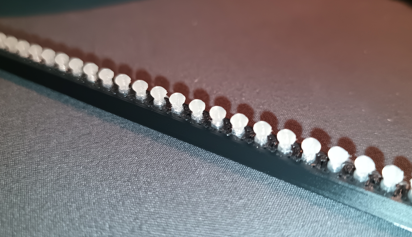
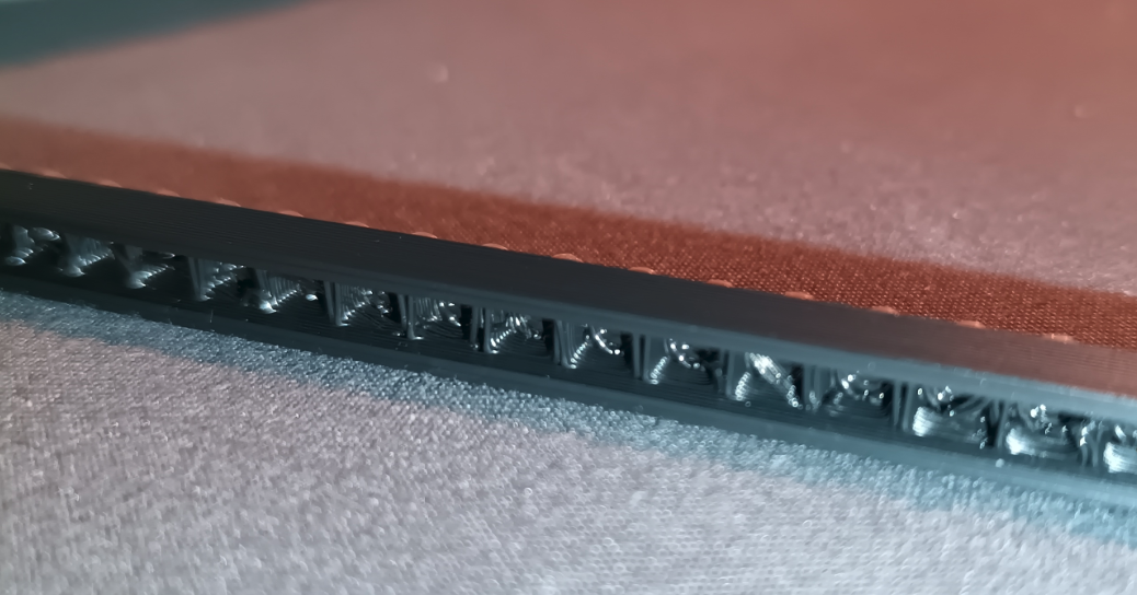
I was going to try and work out why the bottom of the bulb is more transparent than the main bulb is, but i just opened the model up to screenshot it for here, and realized i forgot to lower the fucking bulb down flush with the rafter 😂
Oh well, I think they are fine, i mean, im looking it them up close and in a photo, but when they are in place, they will hardly be visible, so i dont need them to win beauty contents 😂
Besides, FDM printing with a 0.4mm nozzle will only get you so far🤷♂️
Ive printed everything i need to so far, but im putting off actually building it up. I wish i knew why 😭
I was just reprinting a car base (dont ask) and i thought, fuck it, ill double all the speed settings in the slicer, just to see what would happen... and it just printed a perfectly good part.
The time was reduced from 26minutes 23 seconds, to 17 minutes 5 seconds...

Kinda tempted to make platforms / pin wheel for a 10 car waltzer... I should probably finish this one first lmao
I brought a "selphy" from canon about 6 months ago, i got it to print the artwork for the waltzer, but now im second guessing it. My main worry is, the edges of the print. If i print a section of artwork for the shutter for instance, and cut it to size, im starting to think that the white edge of the paper will be visible.
So then i start looking around at other ways people do things like this, and i found plenty of different methods for adding artwork / images to the surface of an object without printing or painting it on. The thing is... they all use laser or inkjet printers, my injet is shit, and never printed color correctly anyway, and the selphy printer uses dye sublimation printing, so that leaves me with laser printing, and laser printers arnt exactly cheap, especially color ones, and even those arnt tremendous at full color images. But.. im considering getting a color laser printer. My fear is, i buy one, and the outcome doesn't meet my expectations.
So i have 2 choices i can see, Use the selhpy printer and hope for the best regarding the white edges, or spend £300 on a laser printer and transfer sheets and hope that it works as i intend...
Seems like an easy choice, but my impulse control is... lacking... shall we say.
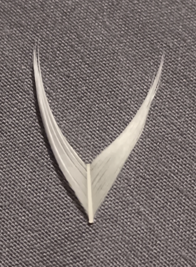
This feather came out of my pillow