Im trying to work out how the best way to arrange / put lights around the windows on the paybox.
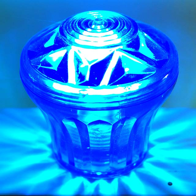
I would like to use the same number as 'bulbs' as the ride im using as a main reference, but its just not gonna be possible, im limited by the size of the leds and FDM printing.
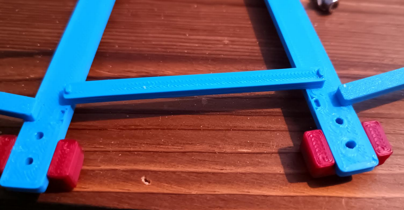
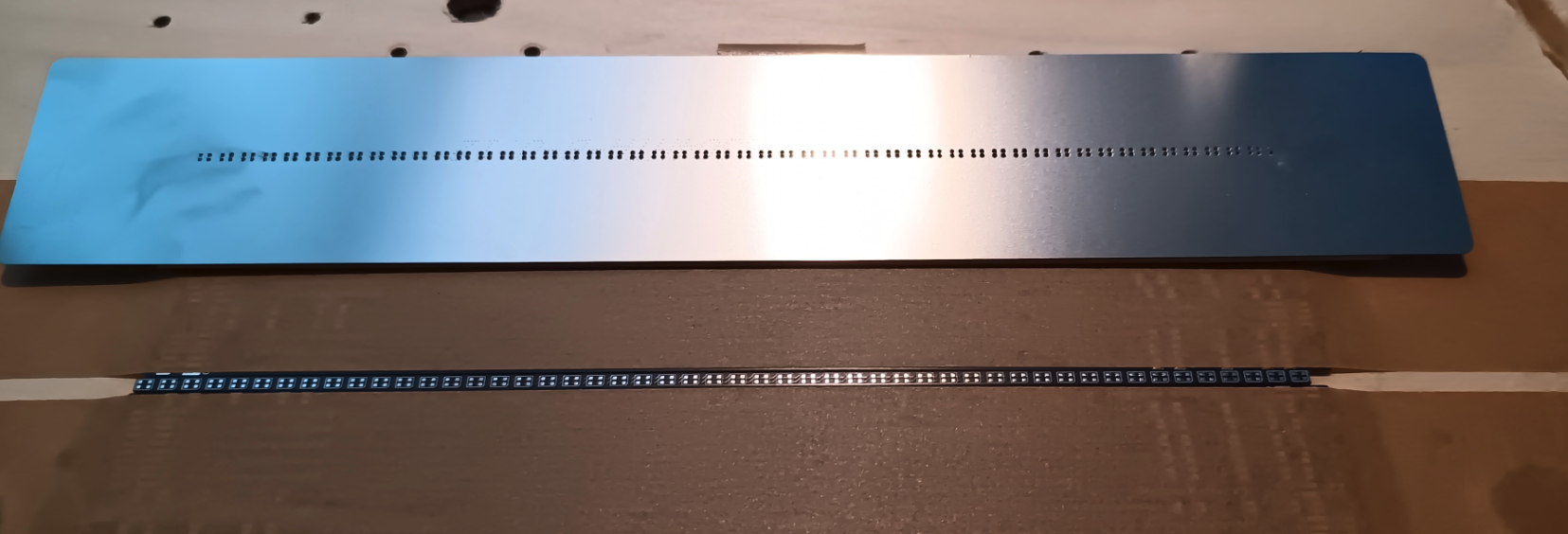
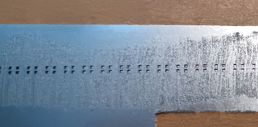
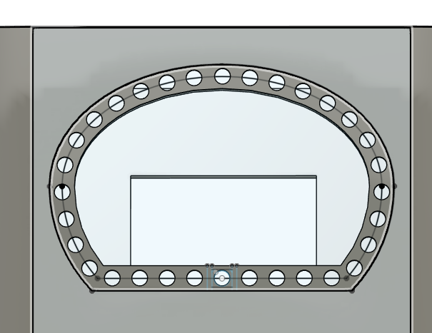
This is the outside of the front window.
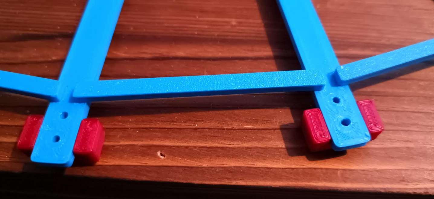
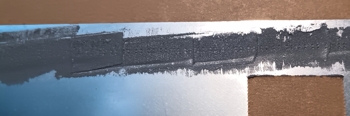
This is the inside of the front window.
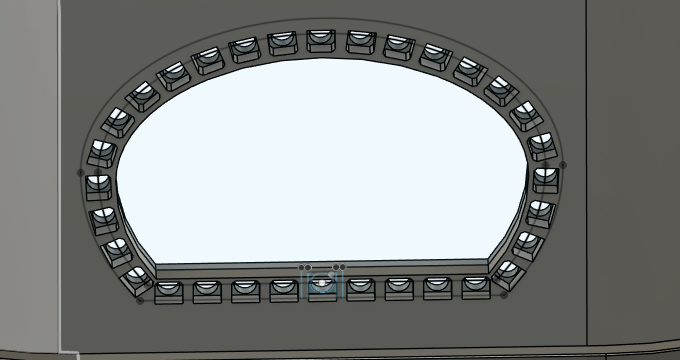
Im thinking of keeping that like that and designing the pcb to stick to the inside of the paybox, with each led being in its own little hole for light isolation.
I was originally going to have the lights and such be a separate piece that just attaches to the outside of the paybox, but im not sure it would hold up very well during printing.
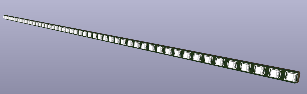
The thing im really worried about, is the curved windows on the sides of the paybox, I can order some petty thin pcbs that should be easy to bend to shape, but i dont know how the solder on the leds will react to a fairly tight curve.