its to hot for soldering 😭
Sad News Alert
Moira Rose is DEAD!
A year or so ago, i was intoxicated and decided i wanted to make an Etch-A-Sketch, but with LEDs, I got kinda far into the project, then gave up on it like most projects. So I have decided to attempt to finish it.
At the moment, im currently in the "where the fuck was i, and what the fuck was i thinking" stage of returning to a project.
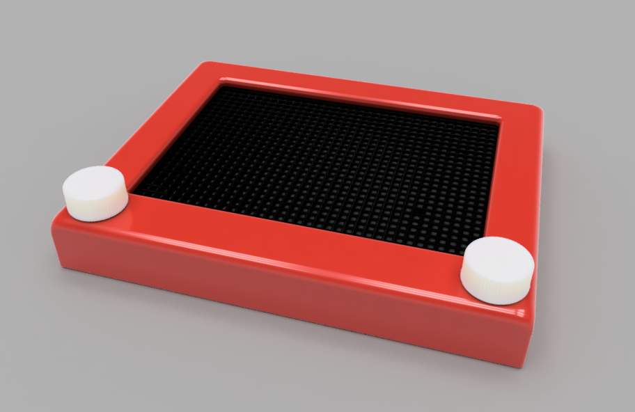
I wanted the LED-A-Sketch (ingenious name, i know😂) to look like a normal etch (i refuse to type its full name again), but with leds instead of whatever they used in etches.
I dont have an etch, and i dont intend on buying one, so ive had to take an educated guess as to the dimensions of a real etch but i think ive got kinda close.
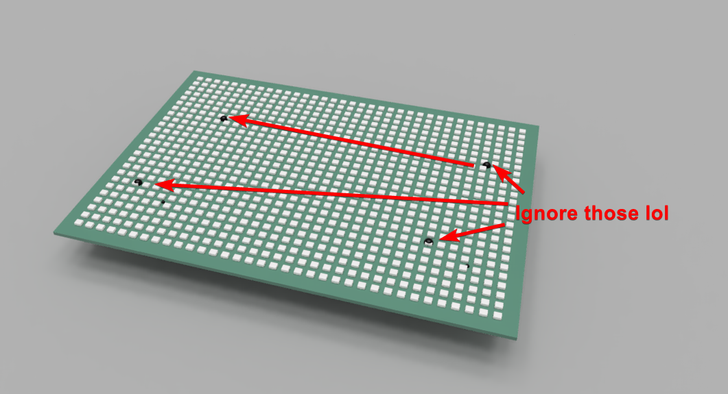
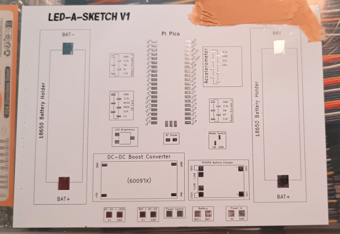
I was looking to use an off the shelf led matrix, but they dont seem to be produced in a size that would work with the original etch dimensions, i did think about LED strips, but they wasn't really suitable for what i had planned. So i decided to just do my own PCB, ive made hundreds of PCBs over the years so its not exactly new to me, and the pcb itself is fairly simple tbh.
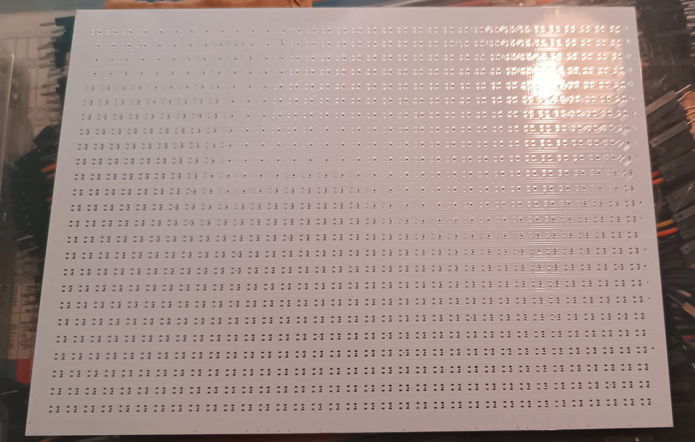
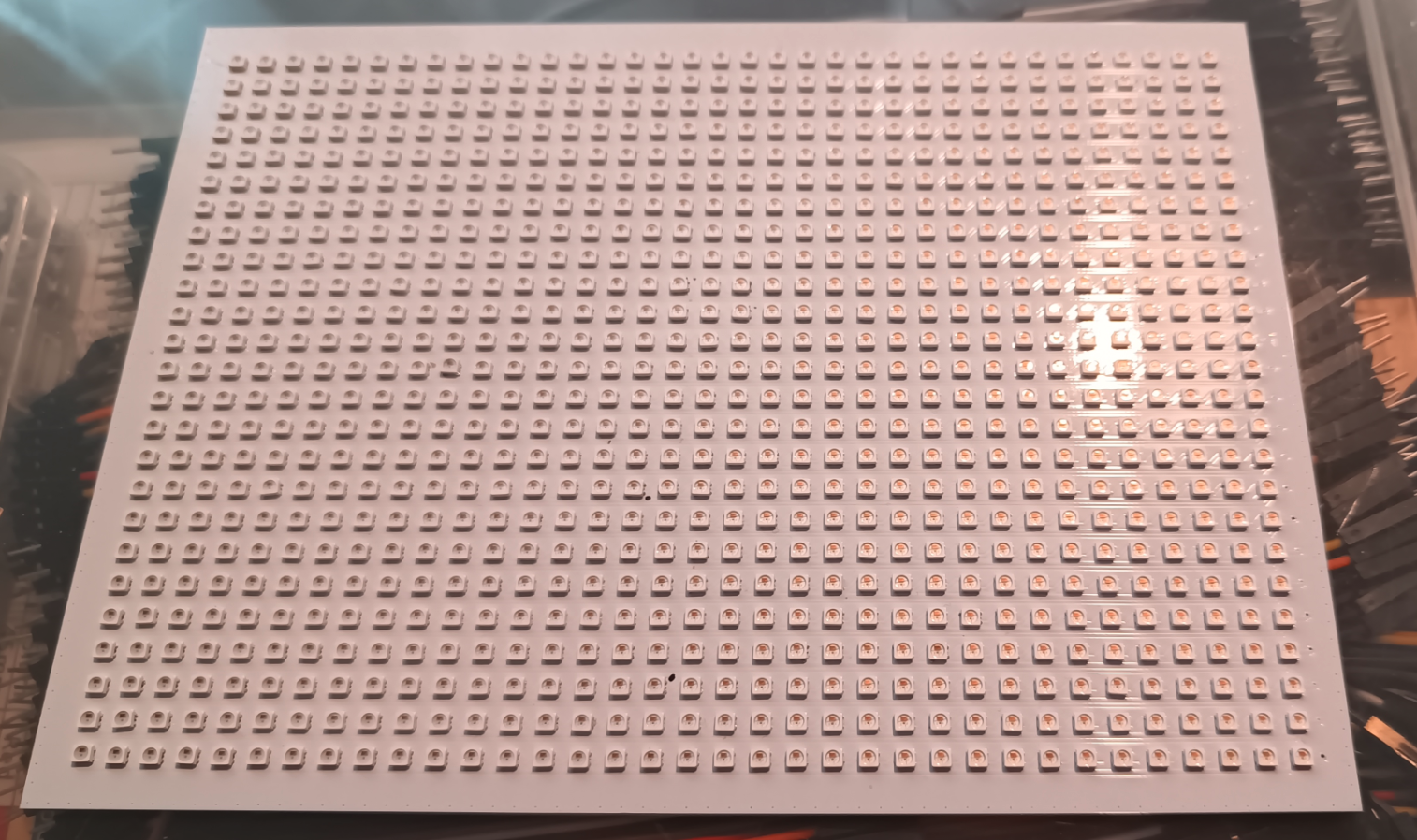
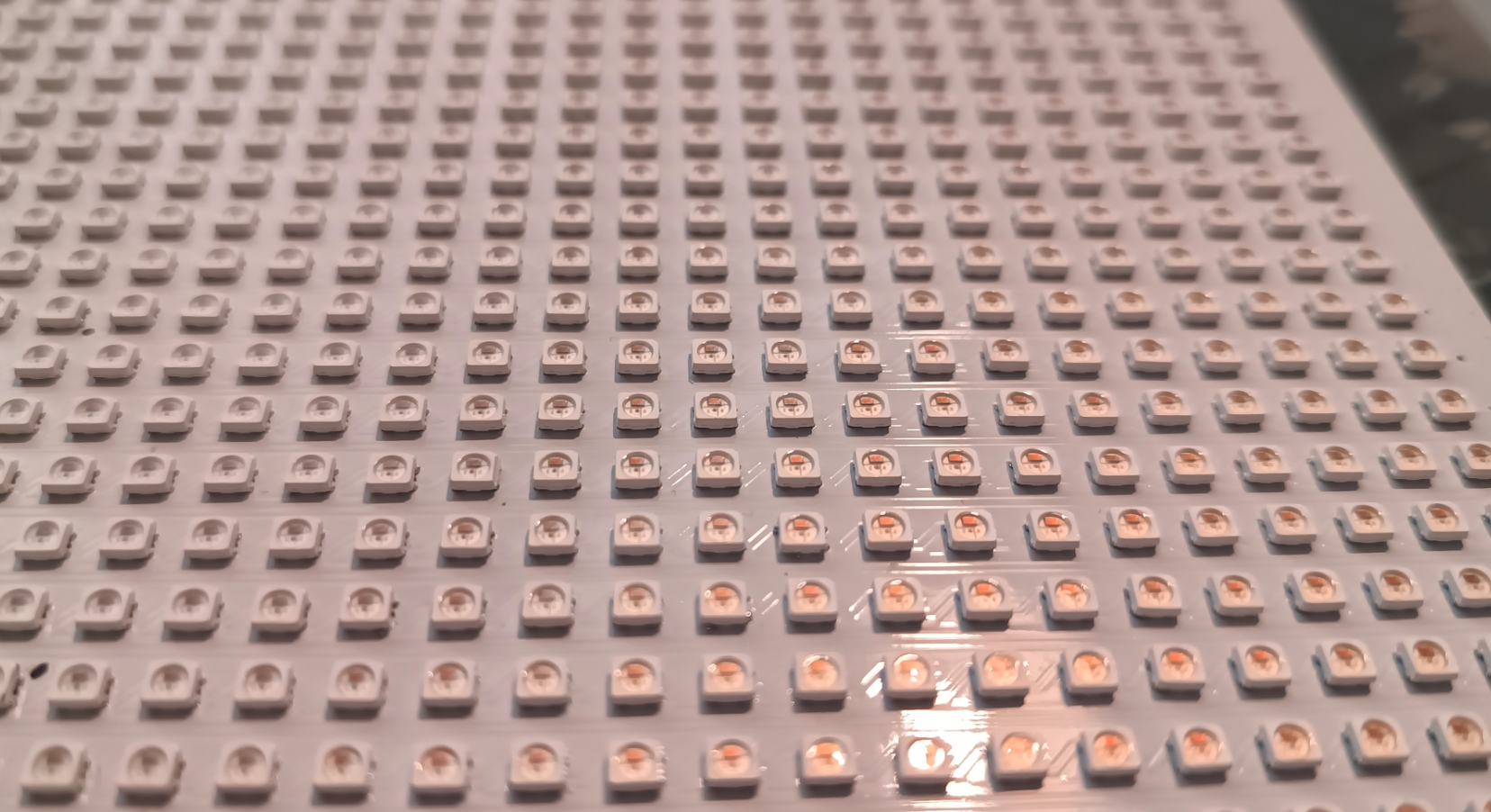
The PCB consists of 875 WS2812C-2427 LEDs in a 25x35 grid.
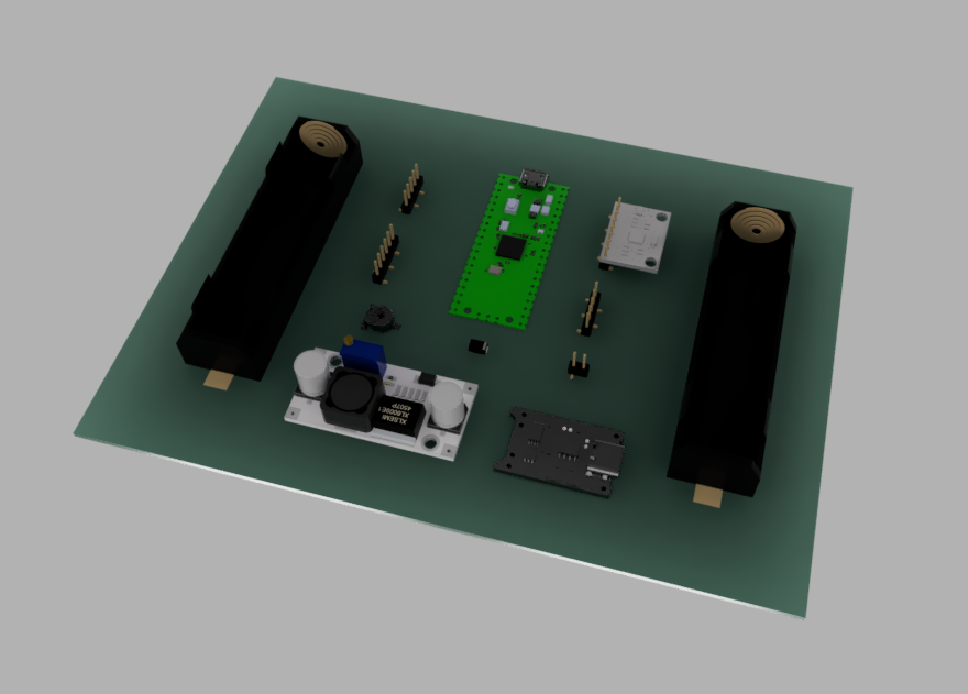
The LEDs will be driven by a PicoPi, It has 2 18650 batteries, 2 Knobs for movement & the potential to add some other things, like an accelerometer (would be cool for shaking to clear the screen).
There is loads of other things i want to implement, but need to get the basic code done first. Some of those things include the aforementioned accelerometer, a "snake" game mode, maybe a sand mode so you can roll the screen and have "sand" flow around, and some other things i haven't thought of yet 😂
Anyway, here is some pics of how it currently looks.
Its too hot to be working on the waltzer, i cant print anything, its to hot to concentrate on designing anything, and im pissed off at multiple things, so the waltzer, for now, will go untouched for an unknown amount of time.
If your wondering why i didn't post yesterday, i spent most of the day building the waltzer and seeing LOADS of things i want to adjust, but would be way to much work to adjust, and by work, i mean reprinting everything.
So i almost just gave in completely and put it on the "future project to finish" pile along with 1000 other things.
Depending how this new connector works, it might still make it to that pile.
Here are some random pictures of its current state.
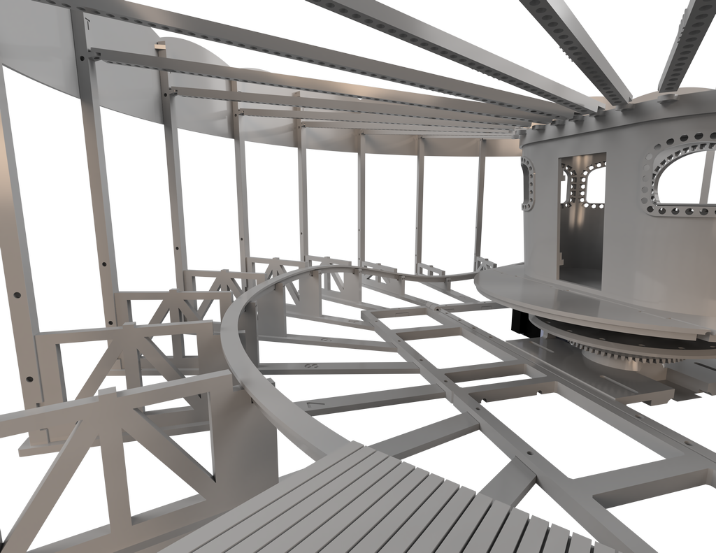
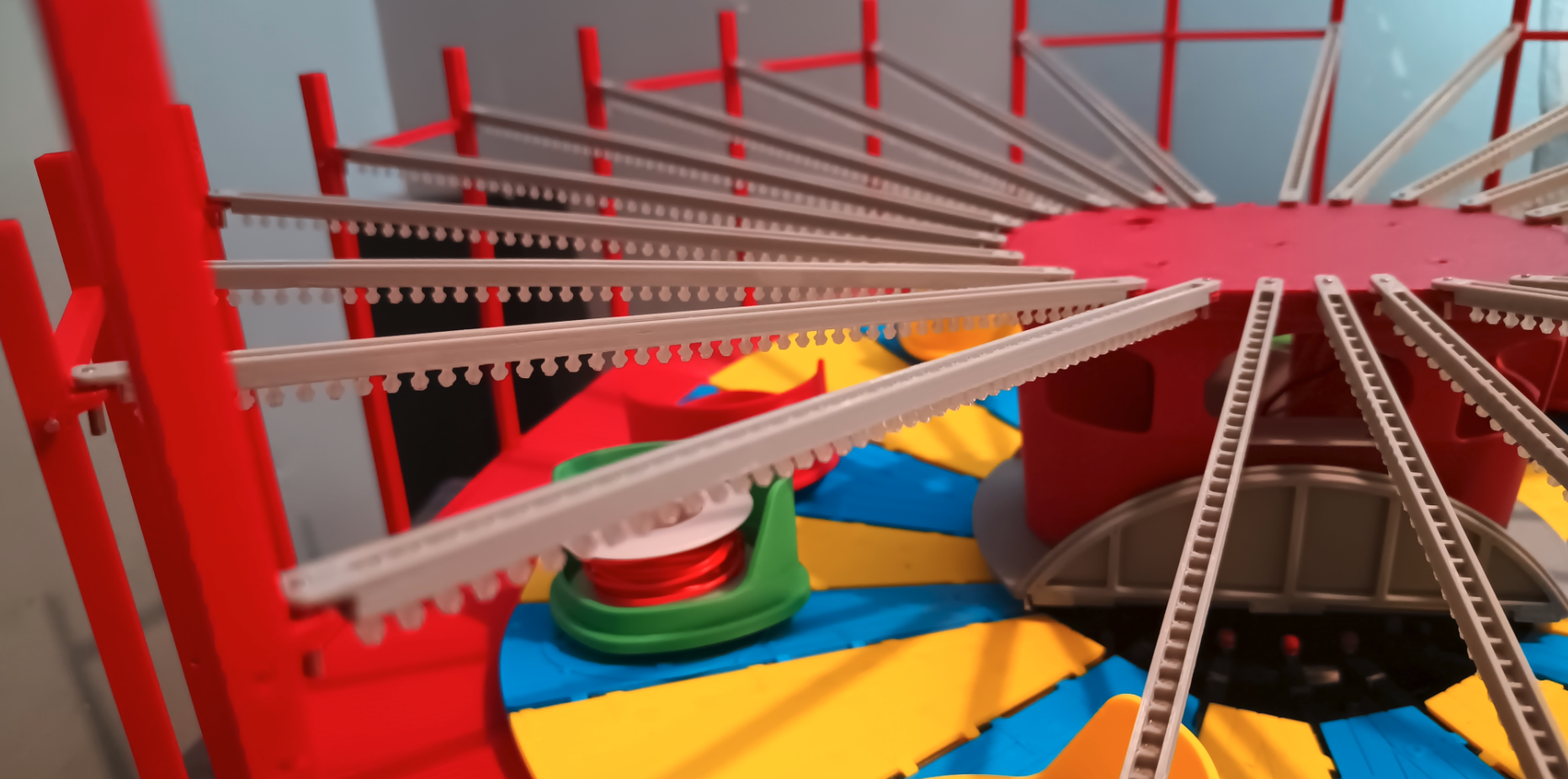
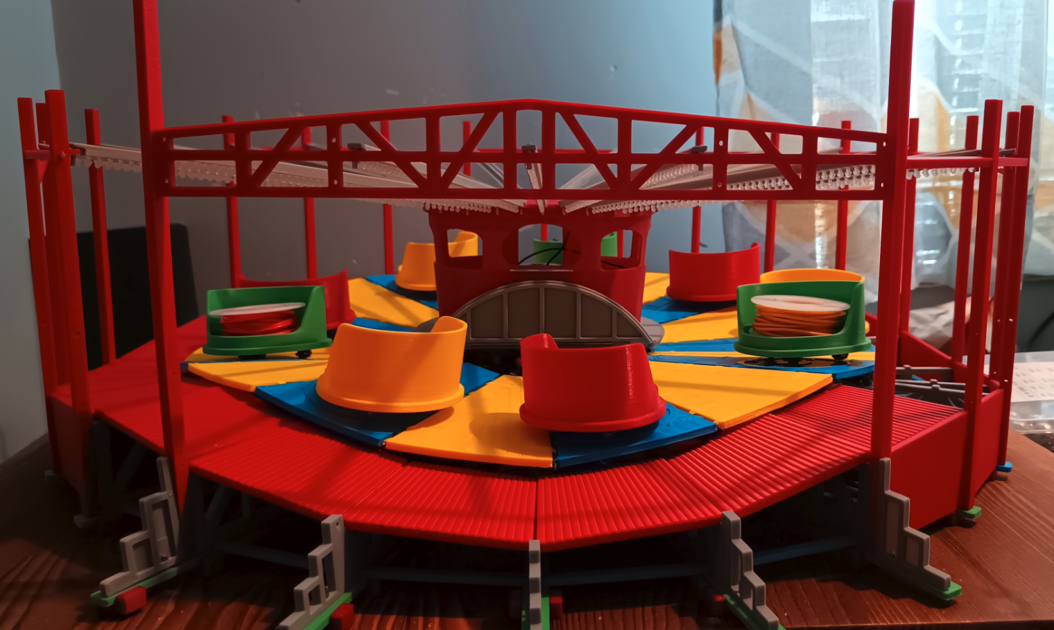
And no, im not happy with the walkways 😒
I have redesigned the connection between the post and the upper cross beam.
It was originally just kinda sat ontop of the pin sticking out the post, but it would just fall off, then i added a little closed gap to try and friction fit the crossbeam to the pin, but that didn't stop it from pulling away from the post, so i have now designed this.
This really is pushing the limits of fdm printing
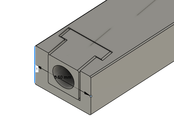
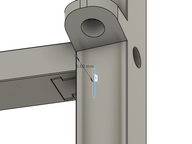
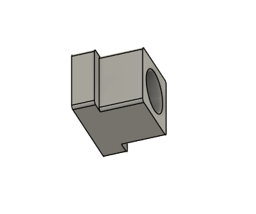
The little connector piece should probably be glued to the pin, but might not be necessary.
The crossbeam pushes onto that connecter piece. The result should be a connection that doesn't move away from the post, and doesn't slide off the pin like the previous design.
Ive been testing some prints of the paybox window frames.
Here is both, one is printed at 45 degrees, the other flat, Both using slim tree supports.
These are straight off the bed, they need a little cleaning.
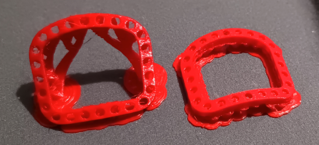
Im conflicted, looking at them in person, i would say the right side non 45degree print looks better, but looking at these photos, the 45degree looks better 🤷♂️😭
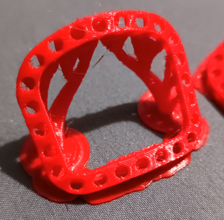
This one has a better surface i would say, yeah it not shiney, but its smoother.
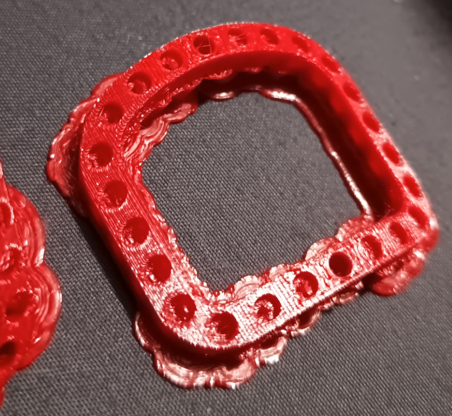
I dunno, i think there are both perfectly acceptable, But printing flat does print faster.
I dunno what the fuck is wrong with me, i really need to start just printing one object and checking it before printing them all 😒
I took a risk and printed the paybox all in one, as in, with the window frames apart of the design, Ill be honest, im not impressed with the print quality.
I think im gonna reprint it without the frames, then adjust the frames to have a little tab that will let me glue them in place.
I dont know how i did it, or how i didn't notice until just now, but when i printed the posts, apparently i forgot to add the top mounting hole for the roundings and what not, So i have to reprint the posts again😭
oh and i had reprint the pinwheel, because somehow the diameter of the holes changed to 2.5mm, which is way to big for 2mm dowels, i just really hope there isn't somewhere else that value changed without me knowing it.
I took the frame apart to rewire it with the thicker gauge wire, but i think i might have left the wires that go into the paybox a little too short, hopefully not, but if it is to short, i can just add a connector or something, at least then i could remove the paybox completely without having to unsolder the connections, but i would prefer to stick with directly soldered wires, i have a distrust for connectors 😒
Something else i noticed when taking it apart to rewire it, i should have added some holes in the frame for wiring to thread through, that way i dont need to zip tie it and it reduces the risk of the wire being snagged by the platforms.
I reduced the hole in the post at the bottom used for connecting to the sleepers, it was a little lose before, so when the pins were glued in, they didn't sit straight, which caused issues with clearance with the gate.
I think thats all 😂
Finally just finished installing the new, slightly shorter hinge bars.
Haven't tried it on the ride yet, but when i was constructing it i realized i could have increased the offset from the platform to the wheel a little bit more, that would help with the scraping on the walkways without having to trim the pin all the way down.
oh well🤷♂️
Ive updated the site to have pagination, it was getting a bit long for a single page 😭
I have no idea how im gonna keep the pcbs bent correctly to fit the windows, i think im just gonna glue them im place, they shouldn't ever need to be removed, unless an led dies, but rides are full of dead lights, so it will make it look more authentic😂
Oh and incase your wonder, i got sidetracked with the window thing, i haven't actually tested the new pinwheel and shorter hingebars
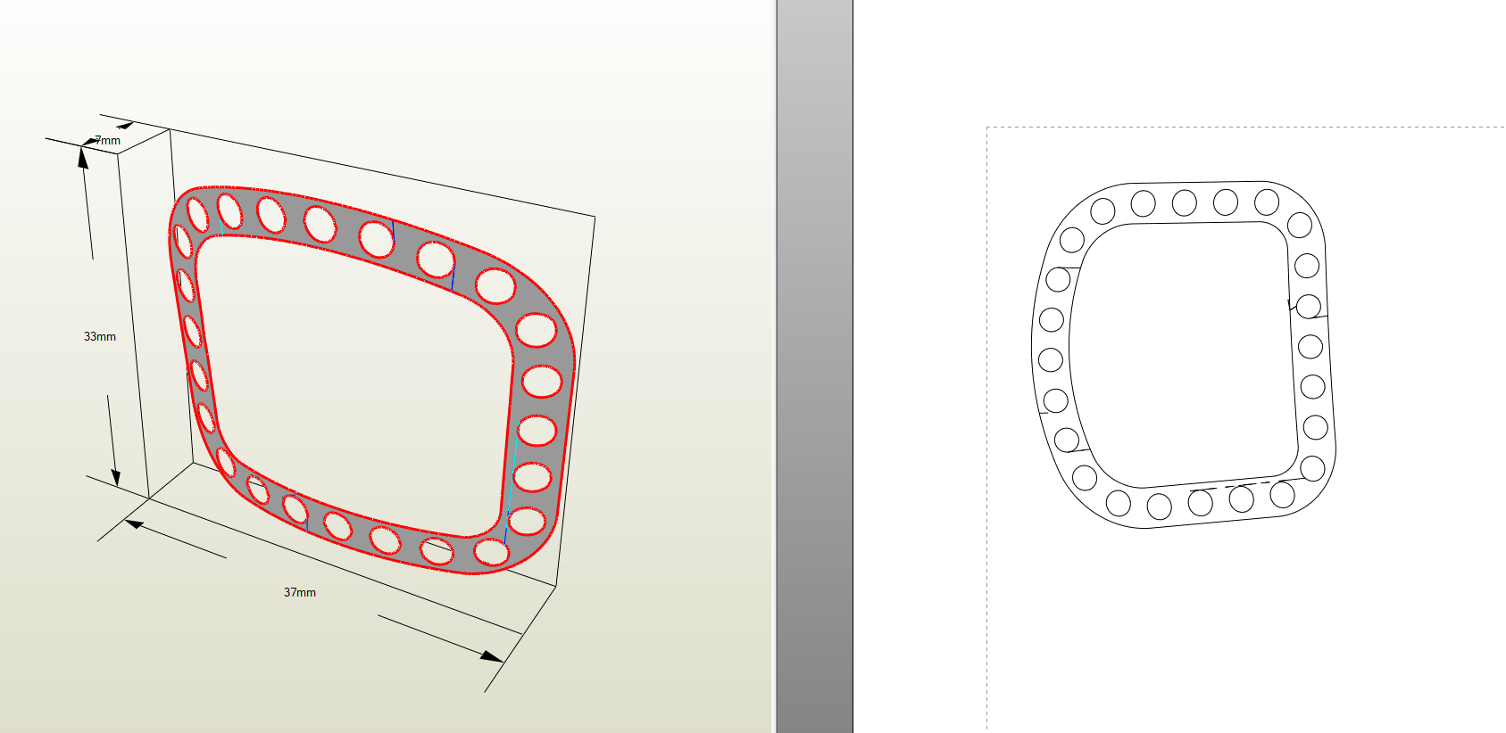
I have just spent FAR to long trying to work out how to export a flat 3d representation of the frame with the holes so i have something to work from for the pcb.
This is what i had to do in the end, just so i dont forget how to do it again😭
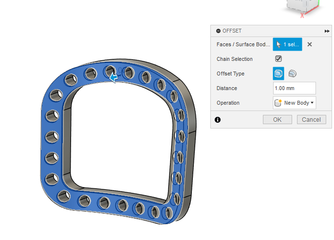
In fusion, select the surface tab and select create > offset
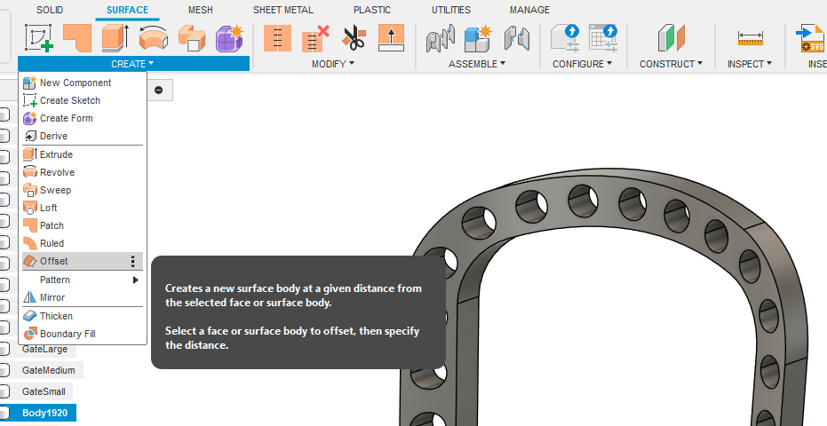
Then offset by some distance, doesn't really matter, i chose 1mm.
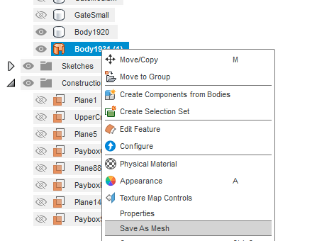
Export the created object as an stl.
Open that stl in Pepakura and click the unfold button, you should get something like this.
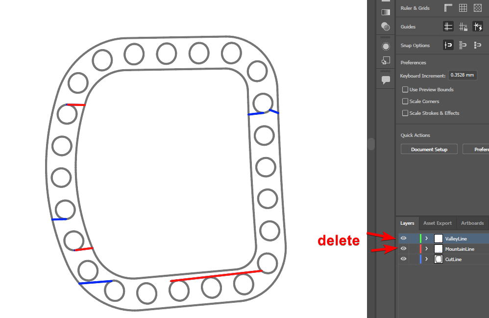
Export that as a DXF file and open it in illustrator
Delete the unneeded layers, Make sure everything that should be joined is, Like the circles arnt actually circles, they are just loads of lines. Make sure they are all "joined".
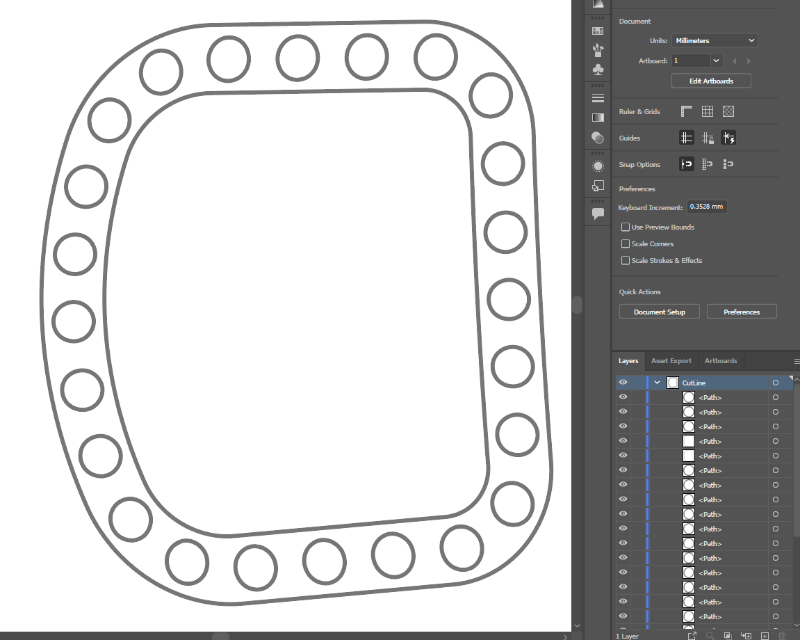
Export that as a DXF from illustrator and import it into fusion, everything should have there own profile
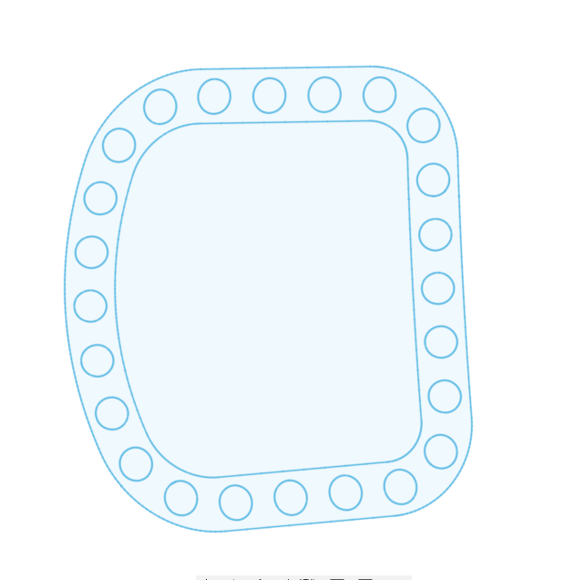
If it does, then the dxf is good, Now i can use that dxf in kicad to make sure my pcb is the correct size with the holes representing the led locations.
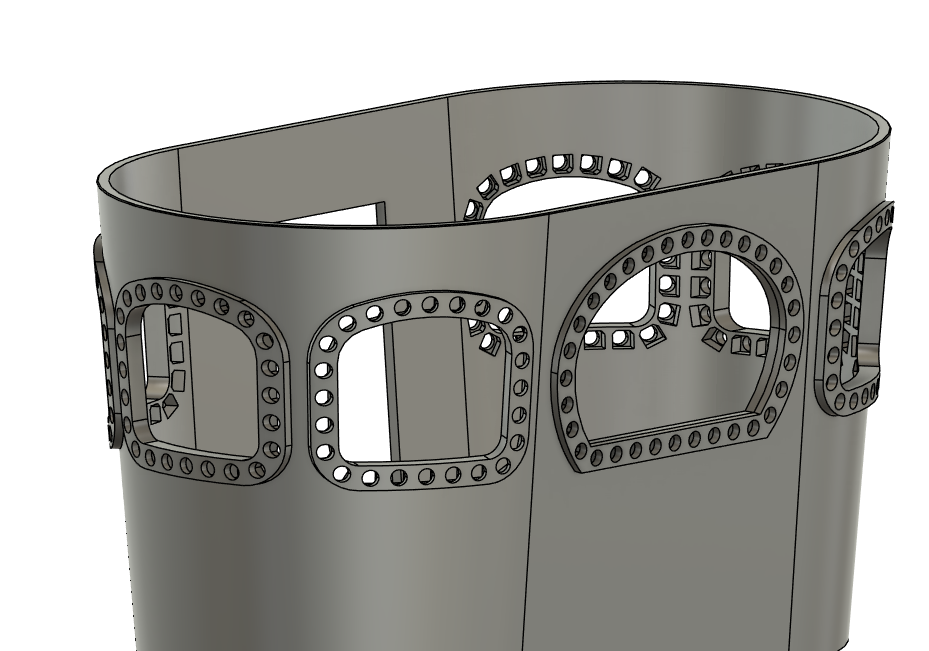
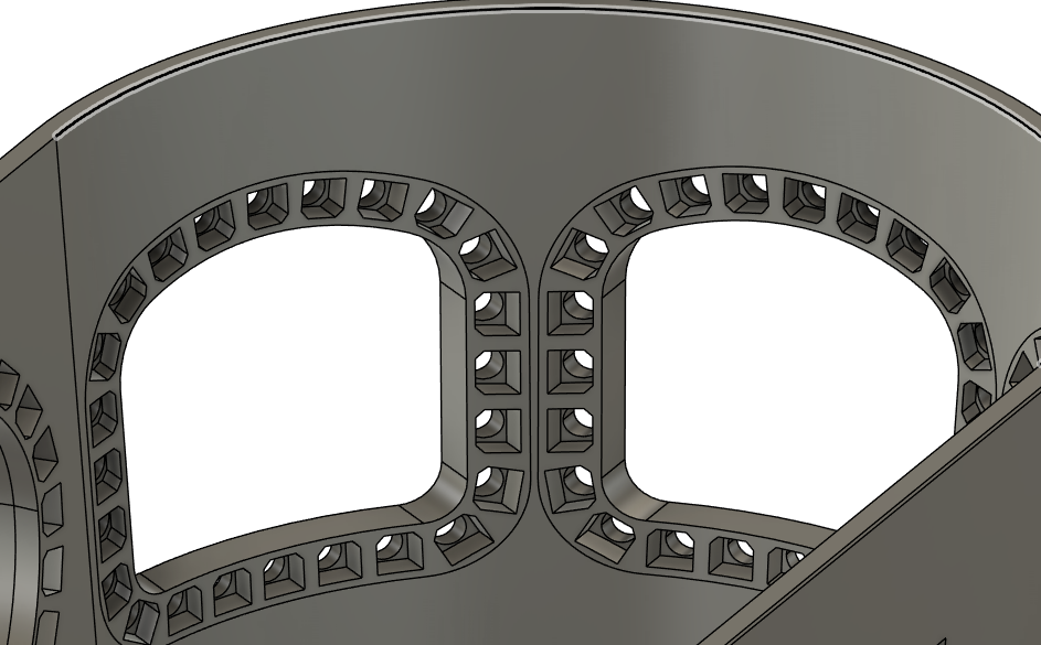
I have kinda done what i needed to do with the paybox window lighting, but i have no idea how this is gonna turn out after printing, assuming it even prints at all.
Im really not confident this will work at all tbh. Even designing the pcb, i will have to account for the curve, but im not entirely sure how to...
I keep thinking to myself, there HAS to be a better way, but i just cannot think of it.
I could print the window frames ect seperatly, so if they do fuck up, i can try again without having to print the entire paybox again, but if i do that, im not sure how im gonna stick the frame into the hole and keep it there.
I cant really explain it well
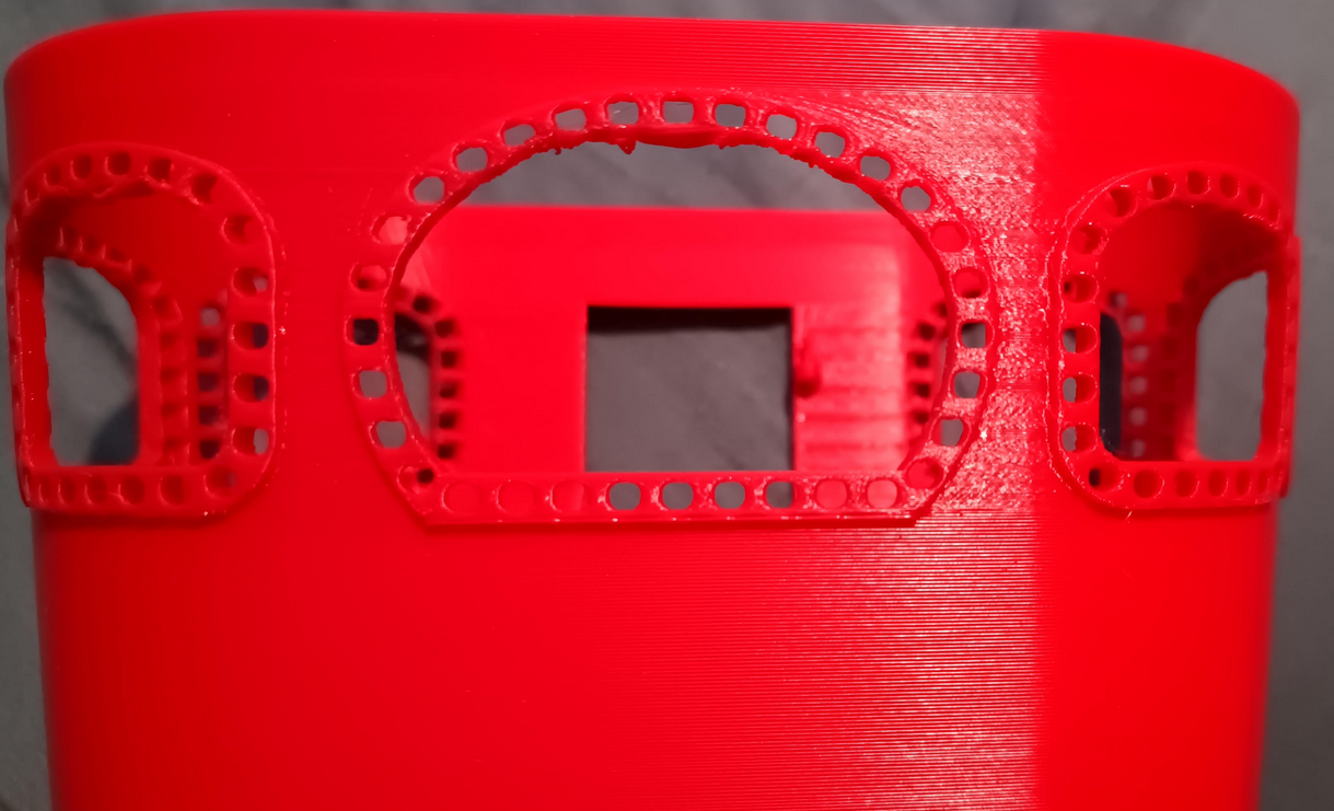
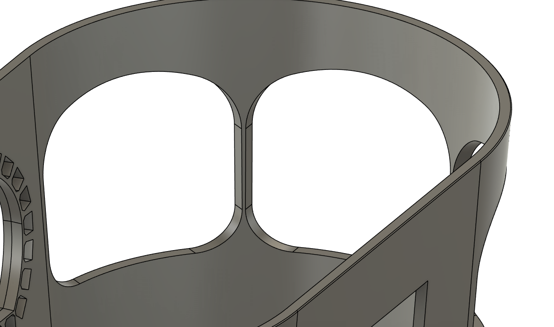
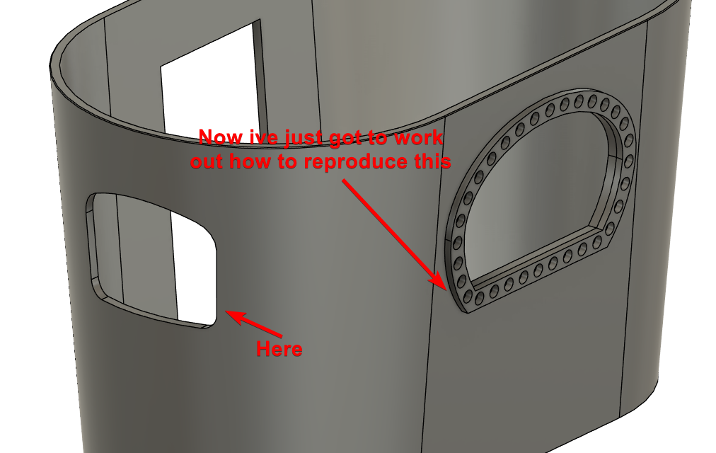
This is the paybox without the window frames / lights.
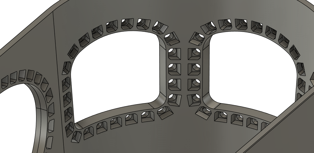
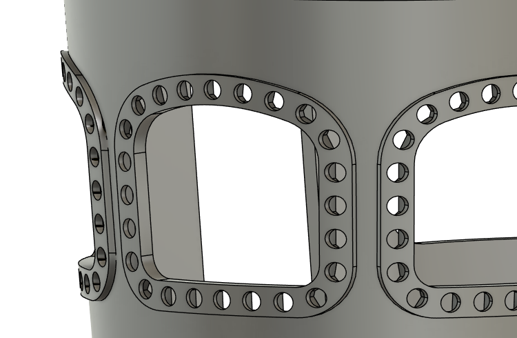
And this is with the frames in place, but not combined with the paybox.
A part of me doesn't even want there to be frames around the windows, but the ride im using for reference has them. I have been looking at other waltzers, and they almost all have lights bordering the windows, but without the frame.
I just reduced the frame thickness by 0.5mm and it looks a little better i think.
For reference, this is what the actual ride im working from has going on.
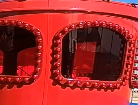
There is quite a bit of lens distortion on the video, so the proportions look.. odd, but you get the idea.
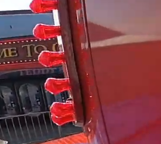
Oh, something else, that pinwheel design is not in anyway representative of the real thing, The real thing has towbar hitch type connectors
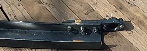
I have no idea how to accomplish that at this scale with 3d printing.
I love the way the real thing works and would love to do something like that, but this is the best i could come up with lol.
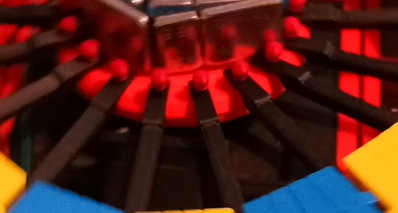
Ignore the silver things on the top, and the blurriness, but its a frame from a video of it running. The little red caps on the pins are shaped like a towbar thing🥺
I have increased the size of the pinwheel to 103mm diameter, which just fits inside the frame edges, and matches photos and videos ive found on the real ride.
It looks a little rediculous, i admit, but hopefully it will work.
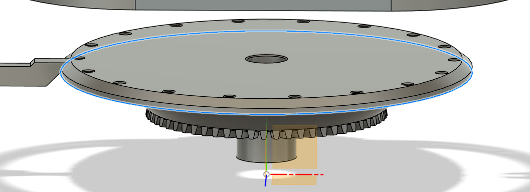
If i still end up having trouble with the pins that hold the hingebar to the pinwheel, i could probably modify this new pinwheel to use a more robust connection fitting. Hopefully the current version of the pinwheel holds the pins more secure.
I had to shorten the hinge bars to account for the large diameter wheel, a plus side being that the hinge bars are less likely to flex now.
Im just printing the new hingebars and the pin wheel. I havent touched the paybox since the last post, im dreading trying to find a way to do what i need with the windows 😭
I am now starting to wonder if the pinwheel being so small might have worsened or even caused the issue with the wheels not touching the track in the valleys🤔
alright, i cant believe im doing this, but i have to rewire the rafter lighting, im not happy with the wires im using, im gonna use some heavier gauge wire.
And since im basically taking the ride down again, im gonna go ahead and increase the diameter of the pin wheel, This should make the ride easier to build up without having to touch the paybox, and be closer to real life size... hopefully.
Showing posts 241-260 of 333