I have no idea why, but i just got an offer on ebay for an old BT telephone.. I think i might buy it...🤷♂️

Moira Rose is DEAD!
I have no idea why, but i just got an offer on ebay for an old BT telephone.. I think i might buy it...🤷♂️
I forgot to add supports for the potentiometer mount😭
If i see any lifting on the current print, ill cancel it, sort the lifitng out, and add the supports obviously.
Nevermind, it seems i was further along in the project than i remembered.
I have started the print, see u in a few hours i guess lol.
I wanna start working on the code for the LED-A-Sketch, but I need to add the controls and such, but if i solder those, i need to print the case so they dont get yanked off. But i dont know if im ready to print the case yet. Im not really sure where i want to put the power jack, i need to work out how to secure the pcb in the case, cause my dumbass didnt put any mounting holes on the pcb. Also, im not sure if i need it, but maybe some ribs to prevent the frame warping / being twisted when in use. hmm
Here is the test code im running and a link to it on github, just incase. (i need to add code formatting to the site too it seems)
https://gist.github.com/PrawnCocktail/b1f38f65085d6e55b9fc4e45bb8dc1ed
#include <FastLED.h>
// Custom WS2812C controller using weird ass timings i just adjusted until it worked.
template<uint8_t DATA_PIN, EOrder RGB_ORDER = GRB>
class WS2812C_280us : public ClocklessController<DATA_PIN, NS(375), NS(1875), NS(750), RGB_ORDER, 0, false, 280>
{
};
#define DATA_PIN 4
#define NUM_LEDS 875
CRGB leds[NUM_LEDS];
void setup() {
FastLED.addLeds<WS2812C_280us, DATA_PIN, GRB>(leds, NUM_LEDS);
FastLED.setBrightness(10); // Increased brightness slightly for better visibility
fill_solid(leds, NUM_LEDS, CRGB::Black);
FastLED.show();
}
void loop() {
// Theater marquee effects
theaterChase(CRGB(127, 127, 127), 50); // White, half brightness
theaterChase(CRGB(127, 0, 0), 50); // Red, half brightness
theaterChase(CRGB(0, 0, 127), 50); // Blue, half brightness
// Rainbow effects
rainbow(10);
theaterChaseRainbow(50);
}
// Theater-marquee-style chasing lights
void theaterChase(CRGB color, int wait) {
for(int a = 0; a < 10; a++) { // Repeat 10 times
for(int b = 0; b < 3; b++) { // 'b' counts from 0 to 2
fill_solid(leds, NUM_LEDS, CRGB::Black); // Clear all pixels
        // 'c' counts up from 'b' to end of strip in steps of 3
        for(int c = b; c < NUM_LEDS; c += 3) {
            leds[c] = color;
        }
        FastLED.show();
        FastLED.delay(wait);
    }
}
}
// Rainbow cycle along whole strip
void rainbow(int wait) {
// Hue of first pixel runs 5 complete loops through the color wheel
for(long firstPixelHue = 0; firstPixelHue < 5*65536; firstPixelHue += 256) {
for(int i = 0; i < NUM_LEDS; i++) {
// Calculate hue for this pixel
int pixelHue = firstPixelHue + (i * 65536L / NUM_LEDS);
// Convert HSV to RGB and set pixel
leds[i] = CHSV(pixelHue / 256, 255, 255);
}
FastLED.show();
FastLED.delay(wait);
}
}
// Rainbow-enhanced theater marquee
void theaterChaseRainbow(int wait) {
int firstPixelHue = 0; // First pixel starts at red (hue 0)
for(int a = 0; a < 30; a++) { // Repeat 30 times
for(int b = 0; b < 3; b++) { // 'b' counts from 0 to 2
fill_solid(leds, NUM_LEDS, CRGB::Black); // Clear all pixels
        // 'c' counts up from 'b' to end of strip in increments of 3
        for(int c = b; c < NUM_LEDS; c += 3) {
            // Calculate hue for this pixel
            int hue = firstPixelHue + c * 65536L / NUM_LEDS;
            leds[c] = CHSV(hue / 256, 255, 255);
        }
        FastLED.show();
        FastLED.delay(wait);
        firstPixelHue += 65536 / 90; // One cycle of color wheel over 90 frames
    }
}
}
Im pretty sure the timing is solid...
Excuse the webp image (and the quality), i despise them, but i cant be bothered to add video support to the site at the moment and the gif was like 18mb 😭
Im trying not to get too hopeful, but i was just looking through this github issue,
https://github.com/FastLED/FastLED/issues/1806
and someone mentioned about the timings needing to be in 125ns increments, which mine wasn't.
Even though he wasn't talking about the WS2812C-2427 or the WS2812C-2020-V1 LEDs that im using, i figured i dont have anything to lose by just increasing the values.
So i adjusted it to be 125 increments whilst keeping as close as i could to the timings that almost worked from the previous post, and it got better. Now just showing different brightness of the same color it should have been. So i increased the T2 timing more and more by 125ns increments until it wasn't glitched.
Im about to test it with some patterns from the adafruit library to see how it holds up, but i THINK i might have cracked it.
Imma try and limit the framerate today and see if that changes anything, then im gonna whack a big capacitor on the power rail and see if that does anything, but i doubt it.
Check it. I (kinda) got the timings thing sorted. It was timings too.
template<uint8_t DATA_PIN, EOrder RGB_ORDER = GRB>
class WS2812B_280us : public ClocklessController<DATA_PIN, NS(400), NS(1100), NS(750), RGB_ORDER, 0, false, 350>
Thats the fastled timings i changed to, i found a post on the github about WS2818 leds, https://github.com/FastLED/FastLED/issues/1407#issuecomment-2408505632
He posted a way to work out the timings based on the datasheet, so i used the timings from the ws2812c datasheet and got the values i used above.
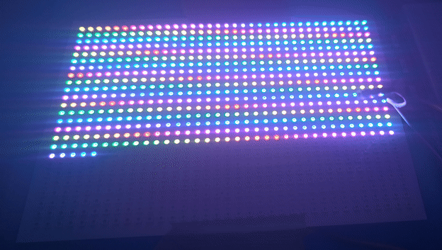
this is the result.
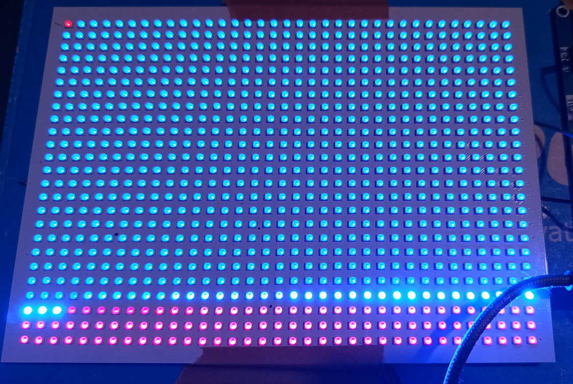
Ignore the first LED, that was the start of the next animation. As you can see, its far from fully working, but its successfully addressing 700ish of the 875 leds, which is way more than before.
The only issue i have is, if i push the timings any higher the leds start glitching again.
The standalone controller only shows me 600 leds, so i have no way to verify if its an issue with timings still, or if its something related to the pcb.
Im 99% sure its timings, as when the animation reaches the glitched out leds, it still turns the leds off in the correct sequence, and the random brightness changes were similar to what we had earlier.
Im not really sure where to go from here to be honest. I could try limiting the framerate? but i dont know if that would actually make a difference. hmmm
ive been looking at the datasheets for the ws2812b and the ws2812c,
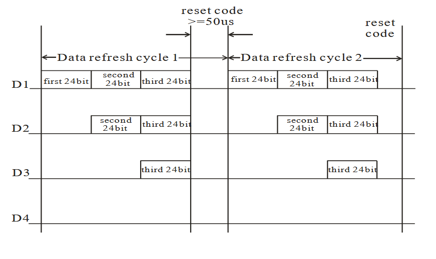
This is from the data transmission section:
WS2812B
WS2812C
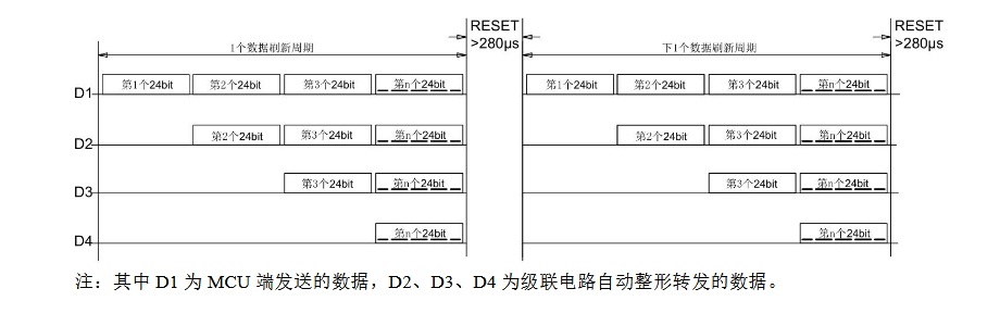
If im reading that correct, the B variant can take a reset time greater than or equal to 50ms, but the C variant needs a reset pulse of greater than 280ms.
So if the reset time being used by fastled B variant is less than 280ms, it wouldn't work on the C variant? But if its more than 280ms, it should work on both the B and C variants?🤔
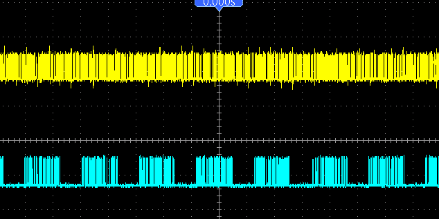
That would explain the scope readings, the blue waveform was the standalone controller, which had much larger gaps between data bursts. The yellow waveform was super close packets, so much so it looks like noise.
I had a look on the github for fastled, but i only saw one post about WS2812C and that was because someone mentioned the "WS2812Controller" template parameter.
I guess im gonna have to sit and look through the fastled source and see if i can see what timing its using for the B variant.
Take a guess which waveform is the standalone controller, and which is the esp32/fastled...
i could hook the standalone controller and the pico pi upto the scope... that might show something
Im looking on amazon, they have a wled based controller on there that uses a esp8266, but its 15, which is more than i would pay for a pack of 5 esp32's, so it kinda feels like a waste, BUT, it might help rule out if its a physical issue or a code issue... ugh😒
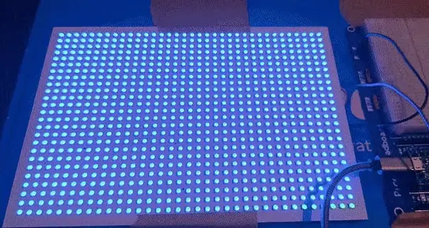
Im still thinking its timing related. When i turn all leds on using the pico pi, you can see the degradation the further you go along the string of leds, until you get to the last row, where only the first 5 or so leds turn on at all, the rest remain off.
If the timing was off by a few microseconds for each led, after a certain amount of leds, it will get so far out of sync, the leds would just be trying to show garbage data, and eventually nothing.
But i know literally nothing about the fastled library, and my c/c++ skills are lacking to say the least
Now im starting to wonder if its a logic level thing, but that doesnt make any sense to me.
So the leds are 5v logic level, that means they need, typically, more than 3.5v ish for the signal to be deemed a "high" level, BUT, there is some margin in that value, 99% of people would be able to run them using 3.3v logic level, which is what comes out of most microcontrollers.
The data signal from the microcontroller only needs to get to the first led. Each LED in the string essentially regenerates the data signal after removing its portion of the data, so the data from the first led to the second led is different than that data from the microcontroller to the first led.
In theory it shouldn't be an issue with the logic level, if it was, the first 140ish leds wouldn't function correctly. The fact they are functioning correctly indicates they are receiving the correct data, and passing it along without issue.
I just talked myself out of it being a logic level issue😂
So after a little bit of research, and a closer look at the "standalone" led controller, it seems most people recommend putting a low value resistor on the data line, i checked on the standalone and it does indeed have an inline resistor on the data output, so i dug out 3 resistors, 100ohm(same as the standalone), a 220ohm, and a 470ohm and it made no difference that i can see.
So its not a missing resistor on the data line.
Ok after i wrote that last post, the led-a-sketch was bugging me, it made no sense that the standalone controller works, but fastled doesn't, So i thought maybe i was misremembering, and the standalone controller didn't work on the led-a-sketch.
I just tested it again, this time hooked up to a beefy power supply, cause the standalone controller doesn't appear to let you adjust the brightness, so they are full bright, which not only makes my eyes hurt, also uses a shit-ton of current.
It works fine... Only 600 of the LEDs are being used, but i assume that's because the string of LEDs i received the controller with was 600 LEDs.
Thats proof that the pcb is functional as i expected it to.. right? So it HAS to be a timing issue, or some other issue not present in the standalone controller.
Here is a picture of the controller, its marked as HJHX001B, I think im gonna take the heatshrink tubing off of it and see what chip its using.
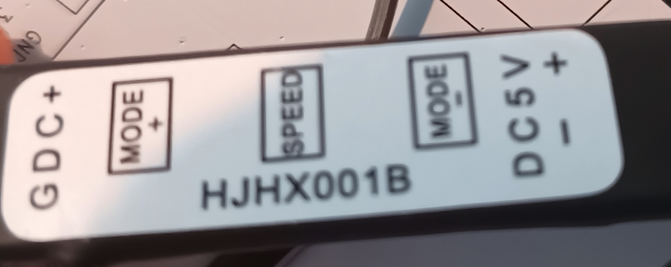
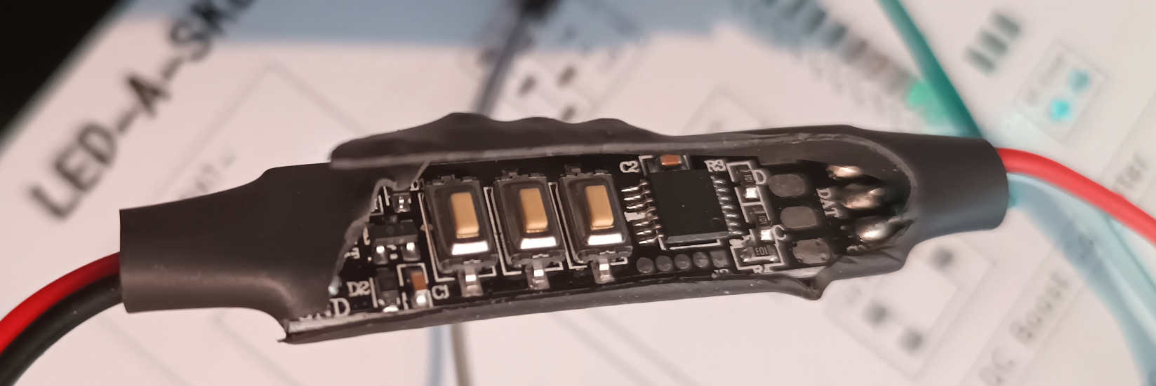
What a surprise, Its a chip with no markings at all. Fucking annoys me that they do that. Better than a blob chip tho i suppose.
I just checked, and the LEDs that the controller came with are WS2812B LEDs, which means the WS2812B LEDs are compatible with the C variants🤷♂️
I got a lot of research to do i suppose, but im not exactly counting on it being any use😒
I dont really know what to do... I have no motivation for anything, I want to play a game, i want to work on the waltzer, or the led-a-sketch, and all my other projects, but i just have no motivation to actually DO it 😔
Like yesterday, i was working on the led-a-sketch, but the leds keep glitching out and i have no idea why, the 5v supply is solid (and not noisy), the data lines are short, ive tried 2 different micro controllers incase its a timing issue, but it still just starts glitching out.
I know there is a limit to the number of leds you can actually address, but according to evidence ive found online and in the datasheet, the limit is usually beyond 1000+, im using 875, and i get the glitching after the first 140ish leds. I dont know why, the standalone controller that came with some led strips i have worked without issue, so im 99% sure its not the soldering / pcb, If it was, the standalone controller would have shown issues too.
The other thing that makes me think its a timing issue is that if i run the leds and force 400Khz speed using fastled, they kinda work...
One of the tests i was running in my code was just showing a single row, in red, and looping through each row. The way i could see if there was any issues and have a good idea of where the issue starts.
What was happening with that test when using 800Khz, the first 140 leds would work fine and slowly start to get worse after that. But when running at 400Khz, it would show the first row, then turn all leds on to orange, then show the second row, then turn all the leds orange, rinse and repeat. That wasn't what should have happened, it should have just showed each row sequentially, i dont know why it was showing all leds orange between each row, but each row worked as i expected (except the orange obviously), which kinda tells me its a timing issue, but the ws2812 leds dont support running at 400Khz, only 800+.
It could be that, despite what the datasheet says, the ws2812c leds arnt timing compatible with the ws2812/b leds. But im sure i would have seen something about that somewhere. When searching for anything relating to ws2812c, my own fucking website (not this one) shows up on the first page of google results, so there must really be nothing out there about the C variants of the LEDS.
kinda wanna work on the waltzer again, this led-a-sketch is being a bitch😒
i wonder if people realize that if the stopkillinggames.com petition reaches its goal, fuck all will actually be done. It will go though the motions, but they wont actually implement a law that makes devs / publishers sunset games in a way that benefits players. At most it will have a 10 minute discussion by a bunch of geriatric fools who know nothing outside of there little bubble and then never mentioned again💀
🥵